The ROSPHERE γ-ray spectroscopy array
Contact persons: Andrei TURTURICA, Constantin MIHAI
Many of the experiments performed at the 9 MV Tandem of the "Horia Hulubei" National Institute of Physics and Nuclear Engineering
(IFIN-HH) in the last years were focused on the measurement of lifetimes of nuclear states. A wide range of such lifetimes was covered,
from tens of femtoseconds by using the Doppler Shift Attenuation Method, to picoseconds using the RDDS method and to nanosecond range
using the newly developed in-beam fast-timing method. The setup used in these experiments was in continuous improvement by increasing
the number of detectors, using various detector types and changing their geometry. By consequence, a new array was needed, with a stable
geometrical setup and an improved flexibility.
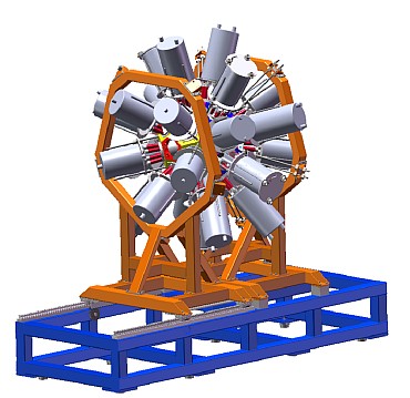
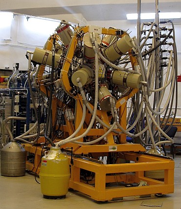
Recently a multidetector setup dedicated to γ-ray spectroscopy studies was built and installed. ROSPHERE (ROmanian array for SPectroscopy
in HEavy ion REactions) is composed by a total of maximum 25 detectors of two types: Compton suppressed HPGe detectors and fast LaBr3(Ce)
scintillator detectors. It is a powerful instrument for lifetime measurements using the in-beam Fast Electronic Scintillation Timing (FEST)
method or, together with a state of the art plunger device, using the Recoil Distance Doppler Shift (RDDS) method. If the experiment
requires high resolution and high efficiency, ROSPHERE can be operated as a full HPGe array.
Two types of coaxial p-type HPGe detectors are used, type a produced by ORTEC and type b produced by CANBERRA. Their relative efficiency is about 50-60%.
These detectors require two types of BGO shields and mounting flanges. For high resolution detection of low energy photons, planar LEP
detectors can also be mounted. The LaBr3(Ce) scintillation crystals are of various shapes and sizes and their readout is provided by
several types of photomultipliers.
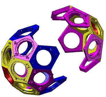
Geometry: ROSPHERE have a spherical geometry, and consists of five rings, each with five available positions for detectors. Their angles with respect
to the beam axis are 37°, 70°, 90°, 110° and 143°. This geometry was suggested by the requirements of compatibility with the plunger
device and sensitivity to the Doppler effect, good sensitivity for DCO measurements in order to obtain multipolarity information and
flexibility in mounting large volume HPGe or LEP detectors (with their BGO shields) or LaBr3(Ce) scintillators in any position.
The design of each flange allows the mounting of the BGO shields in a fixed position, while the HPGe detectors slide in place so that the distance
between the target and detectors varies for each type of detector depending on the ring. LaBr3(Ce) detectors can be mounted at variable distance
to the target, the minimum being 150 mm.
HPGe detectors: The p-type coaxial HPGe detectors, manufactured by ORTEC or CANBERRA (type a or b) have a relative efficiency of minimum
50% and a typical resolution (FWHM) of 1.9 keV at 1.33 MeV.
Both types of BGO shields, custom designed and manufactured by Scionix Holland BV, consist of 8 trapezoid shaped BGO crystals optically
separated, their readout being made by 8 Hamamatsu PMTs (R6094 for type a or R3998 for type b). Their energy resolution is typically
of 18% at 661 keV.
A maximum number of four planar HPGe detectors can be mounted with type a BGO shields. Their energy resolution (FWHM) at low energies
are 0.6 keV at 122 keV and 0.4 keV at 5.9 keV.
All the (maximum) 25 HPGe detectors are cooled and periodically refilled using an Auto-Fill control system built at IReS Strasbourg for the CLARA array.
LaBr3(Ce) detectors: These scintillators are used for in-beam fast-timing lifetime measurements, the method being developed by our group.
They have a high efficiency and excellent time resolution (between 100 and 300 ps depending on the crystal size) and energy resolution
(about 2-3% at 662 keV). Crystals of various sizes and shapes are available for the ROSPHERE array
The scintillators are read-out with special photomultiplier tubes with 8 stages in order to minimize the non-linearity amplitude/energy caused
by the high light output per keV. PMT used are Photonis XP20d0 and Hamamatsu R9779.
Electronics and data acquisition: For the data acquisition system of the ROSPHERE array, standard NIM and CAMAC modules are used.
The block diagram have two distinct components. The first part is a standard slow coincidence to select events with at least n HPGe
detectors (most frequently n = 2 or 3). The second part is a delayed coincidence selecting triple HPGe-LaBr3(Ce)- LaBr3(Ce)
coincidences needed in the fast-timing measurements.
The master trigger signal is an OR by either the slow coincidence scheme or by the delayed coincidence scheme. It serves as a common
START for the HPGe Time-to-Digital converter. This master trigger construction is important because it allows simultaneous fast-timing
measurements and measurements requiring HPGe coincidences.
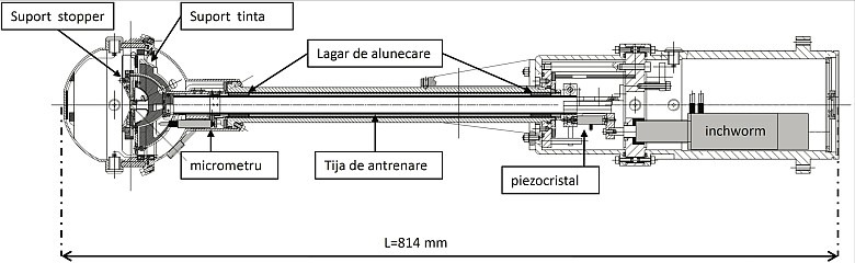
Plunger: A plunger device was built in order to perform RDDS measurements. It is similar with the widely used Cologne
coincidence plunger and consists of three systems:
The distance between target and stopper is kept constant by a feed-back system using the capacitance method.
More details:
Nuclear Instruments and Methods in Physics Research Section A - Paper
ROSPHERE can be arranged since 2021 in a new configuration with up to 25 ELIGANT/ELIADE 3”x3” LaBr3(Ce)/CeBr scintillators, resulting in a high efficiency, medium resolution spectrometer. These detectors have an excellent energy resolution of 1.3% at 9 MeV and timing resolution of ~500 ps. The users have the choice to use a high efficiency configuration with 25 scintillators or a mixed configuration with 1-2 rings (5-10 positions) filled with HPGe detectors and the remaining positions filled with scintillators. In the high efficiency configuration, Geant4 simulations estimate an overall efficiency of 8% at 1 MeV, 2.5% at 5 MeV and 1.2% at 10 MeV. The well-known ancillary detectors ( DSSSD, SORCERER solar cell array, neutron detectors) are also available.
More details: NIM A, Volume 1056, November 2023, 168628 (Link )