9 MV FN Pelletron Tandem Accelerator

Tandem Accelerator
Description

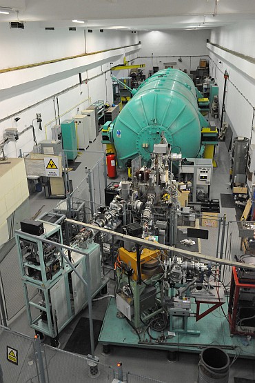
The 9 MV FN Pelletron tandem accelerator was built by the High Voltage Engineering Corporation (HVEC) in 1973 and it was later upgraded from the original terminal voltage of 7.5 MV (FN machine) to 9 MV. The 9 MV tandem accelerator is presently used for basic research, mainly for nuclear structure physics and nuclear reaction physics.

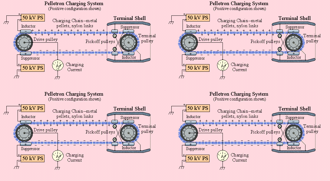
The activity at the tandem accelerator is supervised by the Program Advisory Committee, running at an average of 5500 hours per year. The original configuration of the machine was upgraded starting with 2006. The charging belt was replaced with a more reliable Pelletron system, new ion sources were installed and all the vacuum system and power supply system were installed.

The operating principle of this type of machine is very simple. The high voltage terminal of the accelerator is charged to maximum 9 million volts positive potential. The negative ions from the ion sources are accelerated by the positive potential on the terminal after a selection through the injection magnet (20 degrees bipolar magnet).
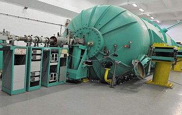
Tandem Accelerator

The ions reaching the terminal region are stripped of electrons using thin foils of carbon (5-10 g/cm2). The ion beam becomes positive and is accelerated away by the same positive terminal potential. The name "Tandem" comes from this two stage acceleration process. The beam is then focused using magnetic quadrupole lenses and analyzed by A/q using a bipolar magnet. The path of the beam through the accelerator and onto the target is under vacuum (a level of 10-7 is achieved using turbo pumping).

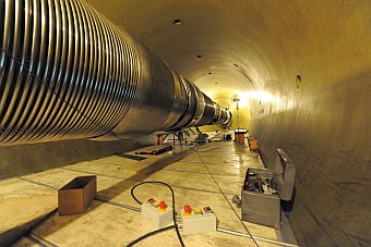
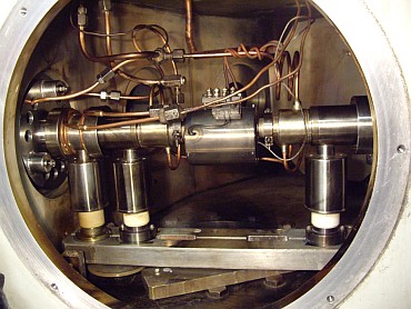
9 MV Pelletron inside view
Acceleration system

In order to keep the high voltage on the terminal the tank of the accelerator an insulating mixture of gases is used (10 bars of SF6 and Nitrogen mixture). The high voltage terminal is kept in its central position by the accelerating column. The column is a succession of stainless steel and insulating glass. The steel pieces are linked with resistors (300 MOhm) and this represents a voltage divider from the maximum terminal potential to the ground potential (the ends of the tank).

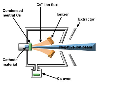
Sputtering scheme


CS Sputter Ion Source
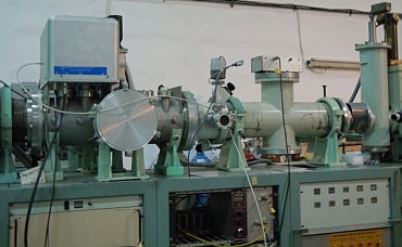
The Cs Sputter Ion Source

One of the two ion sources used for injection of ions into the accelerators is the SNICS II (Source of Negative Ions by Cesium Sputtering) manufactured by National Electrostatics Corporation in USA. The ion source produces a wide variety of ion beams.


The Cs vapors from a heated Cs oven migrate into the ion source. Part of the Cs vapours condensates onto the cooled cathode and another part enters in contact with the heated ionizer (1000 centigrade). The Cs coming into contact with the ionizer is positively ionized and accelerated to the cathode (around 6 kV). The Cs ions sputters atoms from the cathode material. The sputtered atoms from the target material passing through the neutral Cs layer makes the negative ion beam. The negative ions produced are first accelerated by the cathode voltage and then by the extraction element (around 12 kV). Out from the ion source, the beam is pre-accelerated by the 50 kV voltage and injected in the accelerator, after filtering it through the injection bipolar magnet.

Duoplasmatron
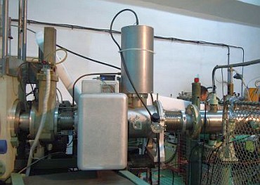
The duoplasmatron ion source with Li/Na charge exchange

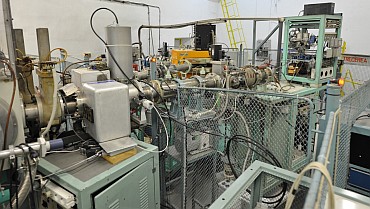
The duoplasmatron ion source delivers positive ion beams from the gases injected into the duoplasmatron head. The ions are extracted from the source with a 20 keV energy and then passes through a Li/Na charge exchange section, in order to obtain the negative ion beam. After this process, the negative ions are injected in the accelerator after passing through the 20 degrees injection magnet. The ion source is mainly used for the delivery of the He- ion beams.

Pulsing system


Pulsing system
Pulsing systems
1. Milisecond pulsing system.

The millisecond pulsing system was built by Dr. Sorin Papureanu and Dorin Moisa and it is practically an electrostatic deflection unit used to chop the continuous beam from millisecond range to hundreds of seconds. The system was mainly used for activation measurements, when decay time of the studied nuclei was in the range of pulsing system. The control module made by Dorin Moisa was able to control the acquisition system in order to start writing the data between two pulses or during one pulse.


2. Nanosecond pulsing system.

The nanosecond pulsing system was installed in 2009. The system is manufactured by NEC and it uses a system for chopping the beam and a system to bunch the already chopped beam. The system uses a 5 MHz RF generator for making the bunches. Typically the bunches are 200 ns apart, but a system called sweeper allows to make this difference bigger to 400, 800 and so on. The efficiency of bunching is around 25% of the continuous beam.


Species of accelerated ions
Ion Energy, MeV Intensity after analyzing magnet, nA
protons 10 300
4He 18.6 500
7Li 27 25
9Be 10 10
10B 10 8
12C 35 250
13C 54 10
19F 14 20
31P 65.8 300
32S 48 250
35Cl 39.3 200
48Ti 60 10
63Cu 80 60

Note: Apart from noble gas species, practically every stable isotope can be accelerated.